Description
The Atomic Force Microscope (AFM) Head Calibration Station is a precision measurement station with sub-nanometer resolution. The station is primarily used for testing and calibrating open and closed loop AFM Heads. It is also used to test the range of piezoceramic tubes and sub assemblies with piezoceremic material.
The station is based on a Zygo Laser Interferometer setup and software, written in LabVIEW, to operate it. Besides controlling the Zygo system over multiple communication protocols, the software also drives a National Instruments data acquisition card. The two analog outputs of the data acquisition card drive a high voltage power supply. The power supply is capable of driving a wide range of piezoceramic materials. The software also supports the capture of sixteen analog channels and monitor multiple digital lines.
Hardware
Zygo Laser
Interferometer System
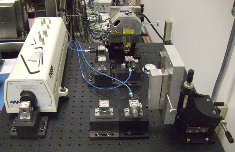
To achieve a sub-nanoscale resolution and accuracy a ZMI Series - Zygo Laser Interferometer system was setup. The interferometer system is driven by two measurement boards and a controller board housed in a box with a VMEbus backplane. The system was designed to simultaneously measure three axes.
The setup is shown in Image 1. It is comprised of a Helium-Neon laser, two fold mirrors, two 50% beam splitters, and three interferometers. The system relies on retroflectors, attached to the target, to reflect the laser into the interferometers.
Communication with the controller can be achieved over RS-232 and/or GPIB for setup and diagnostic purposes. Data capture is possible over GPIB or a special high speed data interface.
 |
| Image 1: Calibration Station CAD Image. |
 |
| Picture 1: Interferometer Setup. |
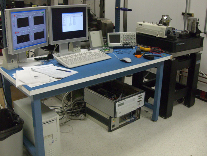 |
| Picture 2: Interferometer Setup Workbench. |
High Speed
Data Capture Board
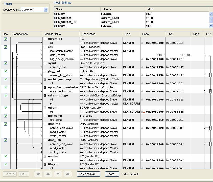
Due to the speed limitation of the GPIB bus to access measurement information from the Zygo controller a special high speed data access board was designed. The board is based on an Altera Cyclone III FPGA.
On the one hand, the board communicates with the Zygo controller's so called P2 port consisting of an address bus and a data bus. On the other hand, it sends captured data over USB and can be configured over RS-232.
The high speed data capture board increased the data capture bandwidth from 100 Hz to 16 KHz.
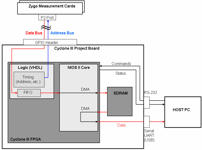 |
| Figure 1: A Block Diagram of the High Speed Data Capture Board. |
Software
Download
| 3D Design | WRL File | ( VRML Viewer or Plugin Required) |